As described here, is a non-contact optical method for surface height measurement on 3-D structures with surface profiles varying between tens of nanometers and a few centimeters. It is often used as an alternative name for coherence scanning interferometry in the context of areal surface topography instrumentation that relies on spectrally-broadband, visible-wavelength light (white light).
Basic principles[edit]
Interferometry makes use of the wave superposition principle to combine waves in a way that will cause the result of their combination to extract information from those instantaneous wave fronts. This works because when two waves combine, the resulting pattern is determined by the phase difference between the two waves—waves that are in phase will undergo constructive interference while waves that are out of phase will undergo destructive interference. While white light interferometry is not new, combining old interferometry techniques with modern electronics, computers, and software has produced extremely powerful measurement tools. Yuri Denisyuk and Emmett Leith, have done much in the area of white light holography and interferometry. Currently, most interferometry is performed using a laser as the light source. The primary reason for this is that the long coherence length of laser light makes it easy to obtain interference fringes and interferometer path lengths no longer have to be matched as they do if a short coherence length white light source is used. For an interferometer to be a true white light achromatic interferometer two conditions need to be satisfied. First, the position of the zero order interference fringe must be independent of wavelength. Second, the spacing of the interference fringes must be independent of wavelength. That is, the position of all interference fringes, independent of order number, is independent of wavelength. Generally, in a white light interferometer only the first condition is satisfied and we do not have a truly achromatic interferometer. Even though there are a number of different interferometer techniques, three are most prevalent:
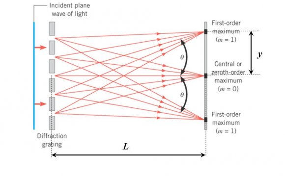
- diffraction grating interferometers.
- white light scatter-plate interferometers.
While all three of these interferometers work with a white light source, only the first, the diffraction grating interferometer, is truly achromatic. All three are discussed by Wyant. Here the vertical scanning or coherence probe interferometers are discussed in detail due to their extensive use for surface metrology in today’s high-precision industrial applications.
Interferometer setup[edit]
Figure 1: Schematic layout of a White-light InterferometerA CCD image sensor like those used for digital photography is placed at the point where the two images are superimposed. A broadband “white light” source is used to illuminate the test and reference surfaces. A condenser lens collimates the light from the broadband light source. A beam splitter separates the light into reference and measurement beams. The reference beam is reflected by the reference mirror, while the measurement beam is reflected or scattered from the test surface. The returning beams are relayed by the beam splitter to the CCD image sensor, and form an interference pattern of the test surface topography that is spatially sampled by the individual CCD pixels.
Operating mode[edit]
Figure 2: Optical setup of a Twyman-Green interferometer with a CCD image sensor.The interference occurs for white light when the path lengths of the measurement beam and the reference beam are nearly matched. By scanning (changing) the measurement beam path length relative to the reference beam, a correlogram is generated at each pixel. The width of the resulting correlogram is the coherence length, which depends strongly on the spectral width of the light source. A test surface having features of different heights leads to a phase pattern that is mixed with the light from the flat reference in the CCD image sensor plane. Interference occurs at the CCD pixel if the optical path lengths of the two arms differ less than half the coherence length of the light source. Each pixel of the CCD samples a different spatial position within the image of the test surface. A typical white light correlogram (interference signal) is produced when the length of the reference or measurement arm is scanned by a positioning stage through a path length match. The interference signal of a pixel has maximum modulation when the optical path length of light impinging on the pixel is exactly the same for the reference and the object beams. Therefore, the z-value for the point on the surface imaged by this pixel corresponds to the z-value of the positioning stage when the modulation of the correlogram is greatest. A matrix with the height values of the object surface can be derived by determining the z-values of the positioning stage where the modulation is greatest for every pixel. The vertical uncertainty depends mainly on the roughness of the measured surface. For smooth surfaces, the accuracy of the measurement is limited by the accuracy of the positioning stage. The lateral positions of the height values depend on the corresponding object point that is imaged by the pixel matrix. These lateral coordinates, together with the corresponding vertical coordinates, describe the surface topography of the object.
White-light interferometric microscopes[edit]
Figure 3: Schematic layout of an interference microscope with Mirau objective.To visualize microscopic structures, it is necessary to combine an interferometer with the optics of a microscope. Such an arrangement is shown in Figure 3. This setup is similar to a standard optical microscope. The only differences are an interferometric objective lens and an accurate positioning stage (a piezoelectric actuator) to move the objective vertically. The optical magnification of the image on the CCD does not depend on the distance between tube lens and objective lens if the microscope images the object at infinity. The interference objective is the most important part of such a microscope. Different types of objectives are available. With a Mirau objective, as shown in Figure 3, the reference beam is reflected back in the direction of the objective front lens by a beam splitter. On the front lens there is a miniaturized mirror the same size as the illuminated surface on the object. Therefore, for high magnifications, the mirror is so small that its shadowing effect can be ignored. Moving the interference objective modifies the length of the measurement arm. The interference signal of a pixel has maximum modulation when the optical path length of light impinging on the pixel is exactly the same for the reference and the object beams. As before, the z-value for the point on the surface imaged by this pixel corresponds to the z-value of the positioning stage when the modulation of the correlogram is greatest.
RELATED VIDEO

Share this Post
latest post
-
 What is grating element? July 6, 2026
 -
 Grating Spectrometers June 26, 2026
 -
 How to Make Holograms for Fake ID? June 16, 2026
 -
 Holographic Packaging June 6, 2026
 -
 Holographic Pen May 27, 2026
 -
 Hologram image projector May 17, 2026
 -
 Hologram Jordan 13 May 7, 2026
 -
 New hologram April 27, 2026