- Diffraction gratings - Fresnel zone plates - Gabor Hologram - Order -
1. Introduction and theory.
Diffraction Grating is optical device used to learn the different wavelengths or colors contained in a beam of light. The device usually consists of thousands of narrow, closely spaced parallel slits (or grooves). Because of interference the intensity of the light getting pass through the slits depends upon the direction of the light propagation. There are selected directions at which the light waves from the different slits interfere in phase and in these directions the maximums of the light intensity are observed. These selected directions depend upon wavelength, and so the light beams with different wavelength will propagate in different directions. The condition for maximum intensity is the same as that for the double slit or multiple slits, but with a large number of slits the intensity maximum is very sharp and narrow, providing the high resolution for spectroscopic applications. The peak intensities are also higher and depend proportionally to the second power of amount of the slits illuminated.
In the beginning let us consider the diffraction from double slit, which consists of two parallel slits illuminated by a flat monochromatic wave. Calculations show that the intensity of the light getting pass through the slits will depend upon the angle j between the direction of the light propagation and the perpendicular to screen:
where 0 is the intensity of the light in the center of diffraction pattern when only one slit is opened, b is the width of the slit, is the distance between the slits, =2p /l is the wave factor, l is the wavelength, D is the difference of the optical lengths of the interfering rays (in the case, for example, when the wave is incident not perpendicularly to the screen or one slit is covered by glass). The first multiplier of the equation in the square brackets describes the Fraunhofer diffraction on one slit and the second multiplier describes the interference from two point sources. The total energy of the light getting through the slit is proportional to b, while the width of the diffraction pattern is proportional to 1/b. For this reason the intensity of the light 0 in the center of diffraction pattern will be proportional to b2. In the limits of the first diffraction maximum we can see interference fringes, where =2/b.
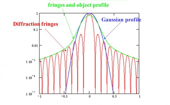
This figure shows the dependence of the light intensity on the angle in the case of diffraction on one slit (red curve) and for two slits diffraction (blue curve). We can see in this figure that the maximal intensities of the interference fringes follow the curve for diffraction on one slit.
Talking about "Fraunhofer" diffraction we mean the far-field diffraction, i.e. when the point of observation is far enough from the screen with the slits. Quantitatively the criteria of the Fraunhofer diffraction is described by the formula:
> 2/l
where is the distance from the screen with the slits to the point of observation. In the close proximity to the screen with the slits the diffraction pattern will be described by the Fresnel's equations
Next, we shall consider the diffraction grating, which consists of N parallel slits. In this case the light waves from every slit will interfere each other producing the interference fringes as shown in figure. Because of diffraction the distribution of the light intensity behind of every slit will not be isotropic (see figure for diffraction at one slit). For diffraction gratings both these effects take place, so the resultant intensity of the light on the screen is described by the equation:
The first multiplier of the equation describes the Fraunhofer diffraction on one slit and the second multiplier describes the interference from point sources.
It is seen from the figure that sin
j is the path length difference between the rays emitted by the slits. If it is equal to the integer number, then the oscillations will interfere in phase magnifying each other. Therefore, we can write the equation for the main maximums of interference pattern: sinj= l, where = 0, 1, 2,| This animation shows the experiment when the width b of the silts is varied, while the distance between them is constant. We can see in the figure that for the narrower slits the diffraction pattern is wider and the visibility is lower. The frequency of the interferometric fringes is the same. |
Share this Post
latest post
-
 CNN hologram technology July 16, 2026
 -
 What is grating element? July 6, 2026
 -
 Grating Spectrometers June 26, 2026
 -
 How to Make Holograms for Fake ID? June 16, 2026
 -
 Holographic Packaging June 6, 2026
 -
 Holographic Pen May 27, 2026
 -
 Hologram image projector May 17, 2026
 -
 Hologram Jordan 13 May 7, 2026